Vertical Milling Center


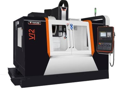
VMC machines, or vertical machining centers, play a pivotal role in modern manufacturing, providing advanced solutions for precision machining tasks. These machines are designed with a vertical orientation and operate using a spindle that moves along the vertical axis, enabling efficient cutting and shaping of materials. By leveraging state-of-the-art technology, VMC machines automate machining processes, which leads to increased productivity and enhanced accuracy in manufacturing. Key features often found in VMC machines include automatic tool changers, high spindle speeds, and robust worktables that securely hold workpieces during machining. Understanding the fundamentals of VMC machines is vital for manufacturers seeking to optimize their operations and maximize output. With the right knowledge and application, VMC technology can significantly streamline production workflows across various industries, solidifying its status as an indispensable asset in the world of manufacturing.
High-speed VMC (Vertical Machining Center) refers to a type of CNC (Computer Numerical Control) machine used primarily for milling operations, which can operate at higher spindle speeds and faster feed rates compared to standard VMCs. These machines are designed to perform complex machining tasks with high precision and efficiency, especially on harder materials like metals.
Key Features of High-Speed VMC
1. High Spindle Speed: These machines can achieve spindle speeds ranging from 10,000 to 40,000 RPM or more, allowing for faster cutting and reduced machining time.
2. Rapid Tool Movement: High-speed VMCs have faster feed rates and rapid traverse speeds, meaning the tool can move more quickly between positions, improving overall productivity.
3. Precision and Accuracy: These machines are designed to maintain high levels of precision, even at high speeds, making them suitable for intricate and detailed work, such as in aerospace, automotive, and mold-making industries.
4. Advanced Control Systems: High-speed VMCs often come equipped with sophisticated CNC controls that allow for more complex programming and better tool path optimization.
5. Cooling Systems: To handle the increased heat generated by high-speed operations, these machines typically include advanced cooling systems, such as through-spindle coolant or mist cooling.
HIGH SPEED Unit 3050 3070 4050 4070
Long/ Trans/ Ver – X/ Y/ Z mm 500/ 400/ 350 700/ 400/ 350 500/ 400/ 450 700/ 400/ 450
Spindle nose to table top – min./ max. mm 300/ 650 300/ 650 300/ 750 300/ 750
Spindle center to column front mm 400 400 400 400
Table height from floor mm 960 960 960 960
Rapid traverse X/ Y/ Z m/min 60/ 60/ 48 60/ 60/ 48 60/ 60/ 48 60/ 60/ 48
Feed rate m/min 40 40 40 40
TABLE
HIGH SPEED E Unit 3050 3070 4050 4070
Size mm 650 x 400 850 x 410 650 x 400 850 x 410
T-slot (no. x size x pitch) mm 3 x 14 x 125 3 x 14 x 125 3 x 14 x 125 3 x 14 x 125
Maximum safe load on table kg 300 300 300 300
Automatic Tool Changer
•
Automatic Tool Changer UNIT
Tool changing system Direct pick-up Twin arm(servo-driven arm)
Tool storage capacity No. 21 24
Pull stud MAS MAS
Max tool with adjacent pocket empty mm 80(100) 65/125
Max tool weight kg 3 6
Tool change time(T-T) s 1.4 1.9
Tool change time(C-C) s 1.7 2.7
High Speed VMC


ROTARY PALLET VMC
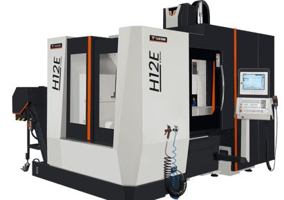
A Rotary Pallet VMC (Vertical Machining Center) is a type of milling machine designed to maximise productivity by incorporating a rotary pallet system. This system allows for continuous machining operations by enabling workpieces to be loaded and unloaded on different pallets without stopping the machine. While one workpiece is being machined, another can be set up on a different pallet, which then rotates into position for machining as soon as the current operation is complete. This seamless transition reduces downtime, enhances efficiency, and is especially valuable in high-volume production environments.
Vertical Machining Centres comes with reliability, stability, and precision. Built with rigid cast iron structure, moving column, high speed spindles, fast rapids, and lower chip-to-chip time for high volume production. Due to its integrated rotary pallet changer, is a better option for high speed operations for your competitive manufacturing.
AC servo drives
AC variable speed spindle motor
LM Roller Guide-ways
Hardened and ground ball screws
Feedback through the absolute encoder
Automatic tool clamping-unclamping
Centralised automatic lubrication
Spindle taper air blow
Electronic counterbalance
3 tier lamp
Hydraulic pallet changer
Rear chip disposal
Rigid Tapping
Hydraulic power pack for pallet changer
Coolant for bed flush
High speed travelling column VMC with rotary auto pallet changer
Cutting zone completely isolated from the machine elements and the operator
Stainless steel lamella covers for X-axis
Compact footprint
Single lift machine
Ring coolant around the spindle
Coolant gun, air gun & maintenance toolkit
Higher spindle power
Chip conveyor in lieu of coolant tank with chip tray
Linear glass scale for X/ Y/ Z
16/ 25/ 40 bar coolant through spindle
AC for electrical cabinet
Provision for 4th and 5th axis rotary table
4th axis rotary table
Servo rotary auto pallet changer
Voltage stabilizer Air nozzle
Air nozzle with M code
Automatic front door
Spindle mounted probe
Table mounted probe
In-line Spindle with 10000 RPM with spindle chiller
pindle torque cont(Option 1)(Option 2) Nm 84/ 115(175 NM)
AXES
X/Y/Z axes mm 650/ 510/ 510
Feed rate mm/ min 1 – 20000
Rapid traverse X/ Y/ Z axes mm/ min 40,000
Pallet top to spindle face (min./ max) mm 200 – 710
Spindle center to column front distance mm 575
• AUTOMATIC PALLET CHANGER
Automatic Pallet Changer- Rotary type Unit
Pallet size mm 800 x 500
T slot ( No./ size/ pitch) – 5 / 18 / 100
Pallet Swing mm 1550
Load capacity of each pallet kg 350
Pallet rotation – Std. ( Opt) type Hyd (Servo)
Pallet change time – Hyd (Servo) sec 12 (4)
Pallet top from ground level mm 1000
• AUTOMATIC TOOL CHANGER
Automatic Tool Changer Unit
No of tools – Std (Option 1, Option 2) No 24 (30, 40)
Maximum tool dia with adjacent pockets empty mm 75/ 125
Maximum tool length mm 200
Tool Weight kg 8
Chip to chip time (mm) as per ISO 10791 – 9 sec 4.5
Pull stud type MAS403 PT40 – 1
• Accuracy As Per ISO 230-2
Accuracy as per ISO 230-2 Unit
Linear axes
Positioning A mm 0.01
Repeatability R mm 0.006
•
• Automatic pallet changer
Automatic pallet changer Unit
CNC System Fanuc oi MF/ Siemens 828 D/ Mitsubishi M80 B(std)
• INSTALLATION DATA
Installation Data Unit
Basic weight of the machine kg ~ 9300
Floor Area for Std. Machine W x D x H mm 2450 x 4800 x 2800
Total connected load kVA 30
Compressed air bar 5
Power supply 415 V ± 10 % AC, 50 ± 2 % Hz, 3 phase
ROTARY PALLET VMC


Rigid structure of the has been designed specially for your long run with profits. The optimally is your best choice for cost effective machining.
The arm type tool magazine uses variable pocket coding. Linear motion guide-ways, variable speed AC spindle drives, and CNC system with digital drive
There are some outstanding features of this vertical machining center
· High speed Travelling column VMC with Rotary auto pallet changer
· Cutting zone completely isolated from the machine elements and the operator
· Stainless steel lamella covers for X axis
· Compact foot print
· Single lift machine
· Flexible machining Center
· Heavily ribbed Base, Column for more rigidity
· Ac servo drives
· AC variable speed spindle motor
· Hardened and ground ball screws
· Feedback through absolute encoder
· Automatic tool clamping – unclamping
· Centralized automatic lubrication
· Spindle taper air blow
· Telescopic covers with wipers
· Full machine guard
· Manual pulse generator
· RS232 serial / USB interface
· Leveling pads
· Maintenance tool kit
· Coolant gun
· Air gun
· 3 Tier lamp
· Ring coolant around spindle
· Rigid tapping
· AC for electrical cabinet
· Front chip disposal
TABLE
Specification Unit
Table size mm 2400 x 810 2400 x 810 2400 x 810
T – Slot (No. / Size / Pitch) mm 5/18/150 5/18/150 5/18/150
Max. Load on table Std. Kg 2500 2500 2500
• SPINDLE & AXIS
Specification Unit
Spindle taper – BT-40 BT-40 BT-50
Spindle speed – Std. rpm 6000 6000 6000
Spindle speed – Opt.1 rpm 8000 8000 8000
Spindle speed – Opt.2 rpm 10000 10000 NA
Spindle speed – Opt.3 rpm 15000 (motorized) 15000 (motorized) NA
• Automatic Tools Changer
Specification Unit
Tool change system – NA Twin Arm Twin Arm
Tool storage capacity – Std. / Opt. Nos. – 24 20
Pull Stud – MAS 403-P40T-I MAS 403-P40T-I MAS 403-P50T-I
Max. Tool dia with all pockets full mm – 75 130
Max. Tool dia with adjacent pockets empty mm – 140 220
Max. Tool length mm – 250 250
Max. Tool weight kgs – 8 15
Tool to tool time sec. – 2.5 4.8
• INSTALLATION DATA
Specification Unit
Floor Space (L x B) mm x mm 5400 x 3450 5400 x 3450 5400 x 3450
Machine height (H) mm 4000 4000 4000
Basic machine weight kgs 17000 17300 17550
Total connected load (Basic standard machine) kVA 50 53 52
Total connected load (Basic standard machine with High Power spindle) kVA 60 63 62
• SPINDLE POWER -STD
Specification Unit
Fanuc / Mitsubishi, Cont./30 min. rating kW 15/18.5 15/18.5 15/18.5
Siemens, cont./ S6-40% rating kW 15/22.5 15/22.5 15/22.5
• SPINDLE POWER – OPT(High power)
Specification Unit
Fanuc / Mitsubishi, Cont./30 min. rating kW 18.5/22 18.5/22 18.5/22
Siemens, cont./ S6-40% rating kW 18.5/27.8 18.5/27.8 18.5/27.8
Rapid traverse – X/Y/Z – Std. m / min 15 15 15
Feed rate mm / min 1 – 10,000 1 – 10,000 1 – 10,000
Double Column VMC


