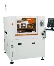

Fully Automatic Visual solder paste printer auto solder machine ASE Solder paste printer for SMT production Auto solder machine for PCB manufacturing Humanized design solder paste printer Wide application range strong versatility
Unique sprinkle automatic cleaning system
Efficient energy-saving wiping paper-saving solder paste printer structure
Unique image solder paste printer processing system
Intelligent printing product mode
Printing range: 400*340mm/510*340mm
Use international universal UVW three axis linkage platform
Specifications
Model : SSSP-01
Screen frames PCB Min Size 370x370mm
PCB Max Size 737x737mm
Thickness 25~40mm
PCB Min Size 50x50mm
PCE Max Size 400x340mm (510x340mm)
PCB thickness 0.4-6mm
PCU warpage <1%
Transport height 900±40mm
Transport direction Left-Right, Right-Left, Left-Left, Right-Right
Transport Speed Max 1500mm/S Programmable
Board Location Support System Magnetic Pin/Up-down table adjusted/ support block
by hand Magnetic thimble/Adjustable lifting platform/ Contour block
PCR Positioning Clamping System side clamping, vacuum nozzle Print head Two independent motorized print heads
Squeegee Speed 6~200mm/sec
Squeegee Pressure 0-15Kg Motor control
Squeegee Angle 60°/55°/45°
Squeegee Type Stainless steel(Standard), plastic
Stencil Separation Speed 0.1-20mm/sec Programmable
Cleaning System Dry, Wet. Vacuum (Programmable)
Table Adjustment ranges X: ±10mm, Y: ±10mm, θ:±2°
Solder paste printing Machine
Repeat Position Accuracy ±0.008mm cpk>1.66
Printing Accuracy ±0.0125mm cpk>1.66
Cycle Time <7s (Exclude Printing& Cleaning)
Product Changeover <5Min
Air Required 4.5~6Kg/cm²
Power Input AC:220+10%, 50/60HZ 3KW
Control Method PC control
Surface Mount Technology (SMT) Has Revolutionized The Electronics Manufacturing Industry Over The Past Few Decades. The SMT Assembly Line, Commonly Known As The SMT Line, Allows For Automated Mass Production Of Printed Circuit Board (PCB) Assemblies With Great Precision And Speed. The Process Of Mounting Electronic Components Directly Onto The Surface Of A Printed Circuit Board (PCB). This Is An Automatic Process, Allowing Electronic Boards To Be Produced Faster And More Accurately Than Ever Before. SMT Lines Provide Numerous Advantages Over Traditional PCB Production Methods. SMT Loader Stencil Printing Machine Pick And Place Machine Reflow SMT Unloader The PCB Are Automatically Moved From One Station To The Next, With Intermittent Docking Stations Located Throughout The Process Line To Allow For Manual Inspection.
SMT PCB Lines
Automatic Soldering Paste Printer
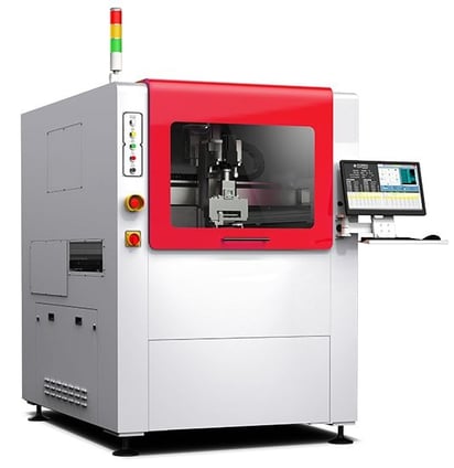

Our PCB Router Machine will also cut down on bit replacement with our router bit depth adjustment system, which automatically shifts up to 5 depth levels. The PCB router bit maximum cutting speed is 50mm per second, while the traveling speed is a maximum of 800mm per second. With a built-in fixture based dust vacuum system, the PCB Depaneling system is sure to be clean and efficient. This prevents warping, and takes full advantage of vacuum strength for the most effectual dust collection.
Key feature of router machine
Solution for stress free depanelization
Fixture-based highly efficient dust vacuum system
Clean and precise depanelization for densely populated PCBs
Advanced image-processing software offers point-and-click operation for programming router paths
Automatic alignment compensation by CCD camera
User-friendly operation
Extended bit life by automatic router bit depth adjustment
Improved tact time
Low maintenance required
Reasonable priceCutting is with clamp, without fixture demand.
Suitable for PCB the high components on its top, and PCB weight is lower than 3kg.
Use CCD to do the vision positioning off-set and alignment which can ensure the precision in cutting.
Unloading can be setting between 0~180 degrees on placing in line then connect the equipment behind of it.
Loading by track; for unloading, there are 3 ways of conveyor, tracking and customized placing board on tray for customer’s selection.
Valid cutting size 500*450 mm
Loading Method Track Delivery
Unloading Method Conveyer belt delivery or track delivery(optional)
Transfer Method The rotatable clamp for taking
Movement Direction Left to Right or Right to Left(optional)
Cutting function Tweening to straight line, L shape, U shape, Circle, Arc
PCB specification weight ≦ 4kg,edge width ≧ 3mm,thickness 0.8~4mm
Repeat precision ±0.01mm
Cutting precision ±0.05mm
Cutting speed 1-100mm/s (Adjustable)
Spindle's speed MAX: 60000rpm (Adjustable)
Tool change type Auto tool change
Broken knife check Included
Operating system Windows 10
Program teaching mode Intuitive teaching by CCD color image input
Control method Precision multi-axis control system
XYZ axis driving mode AC Servo motor
Size of milling tool ∮0.8-3.0mm
Voltage/Power requirement AC220V 50/60HZ 4Kw 1Φ
Pneumatic pressure requirement 0.6MPa, 160L/min
Dimensions(W*D*H) 1252*1859*1735
Weight 770KG
Dust collector
In-line Automatic PCB Router /De paneling Machine
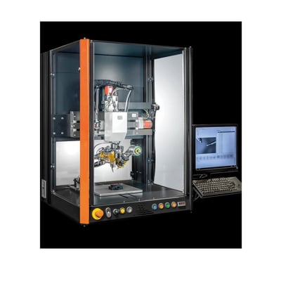

Automatic Soldering Machine increases production with less hands and ensures consistent soldering quality for each joint. Ideal for Automatic PCB soldering - spot Soldering Machine are automated machines designed to perform precise soldering tasks quickly and efficiently. These robots are equipped with advanced control systems and high-precision soldering tools, such as irons, tips, and dispensers, to perform various soldering applications
3-axis and 4-axis soldering Machine are capable of moving in three or four directions, respectively, and can perform a wide range of soldering operations, including surface mount technology (SMT), through-hole technology (THT), and manual soldering. These robots are commonly used in electronics manufacturing, where precision, speed, and consistency are essential.
some of the advantages of using soldering Machine include increased productivity, improved solder quality, reduced labor costs, and a safer working environment. These robots are also highly customizable, and can be programmed to perform specific soldering tasks based on the requirements of the application.
Soldering Machine are an excellent investment for businesses looking to streamline their soldering operations and improve their overall efficiency and productivity.
4-Axis Soldering Machine – Highly reliable and affordably priced
A 4-axis Soldering Machine is that is designed for precision soldering applications. It typically consists of four axes of movement, including X, Y, Z, and a rotary axis. This additional rotary axis allows for more flexibility and range of motion in the soldering process, which can be useful for working on complex or irregularly shaped objects.Some common features of 4-axis Quick soldering robots include high precision and accuracy, fast cycle times, and the ability to program and automate soldering processes. They may also be equipped with various sensors and feedback systems to ensure consistent and reliable soldering results. Soldering Robot increase production with less hand and ensures consistent soldering quality for each joint.
Overall, 4-axis soldering Machine can be a valuable tool for manufacturers and other industrial users who require high-quality, high-volume soldering capabilities. They can help to increase productivity, reduce labor costs, and improve overall product quality and consistency.
Features:
High power heating controller, ensures temperature stability in continuous soldering.
Line Soldering & Point Soldering functions
Control signal O/P & I/P available.
Auto cleaning of Soldering Tip
Hand-held Teaching Pendent for easy programming
Optional Vision System, normally not required
Scope of supply:
4-Axis 400x400 mm Soldering Machine
Hand-held Teaching Pendant
Soldering & Wire Feeding Controller
Soldering & Wire Feeding Head
911G Series Soldering Tip
Soldering Tip Cleaning System
In-line Automatic Soldering Machine
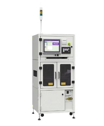

An in Circuit Tester is a tool that can be used for testing the functioning of various electronics components and the overall system of an electronic device. It is used as a non-invasive testing device that is designed to do the task without causing any type of damages to the device or components. It is also very cost-effective and is designed to perform certain tasks without using any kind of complex tools.
Key Features
Scanner boards
Two types of boards are available: scanner boards for speed, and relay boards for high power and precision. A variety of test functions are available to suit individual applications.
Man-Machine interface
Communication with Windows-based PCs via LAN is available. Operation is easy in an environment familiar to everyone.
Strengthened data editing functions
Use these functions to develop and modify groups of test data such as for multi-cut boards or data managed in multiple fi les, by modifying only the necessary parts.
Statistical analysis
Data measured by Model 1220 can be saved to a PC?s hard disk for each board tested. Data is stored in CSV format, which can be adapted to many applications.
Functions combined in one bench-top cabinet
In-circuit testing functions are assembled into a system or line to save space in the testing facility, enabling easy support of cell production.
Macro test
Includes the macro test, a high-performance capability for testing even with only a few measurement points (see page 3 for details)
High-speed test 1
Faster in-circuit testing is achieved by a new measurement board design
High-speed test 2
Optional board parallel testing greatly shortens test time.
Remote self-diagnostics
Self-diagnosis of Model 1220 can be initiated over the Internet, enabling remote maintenance support even at factories located overseas.
Compatibility
Test data from the can be converted. test data can be converted by the 1137-02 data generation software. Data conversion functions also support data from other companies.
System development
Because of its easy network confi guration, customers can operate the system as their requirements demand. Test data from multiple 1220s can be centrally managed by a server PC. Applications can be constructed to include operations such as capturing test history, statistical data and operating conditions of each machine.
In-Circuit Tester (PCB)
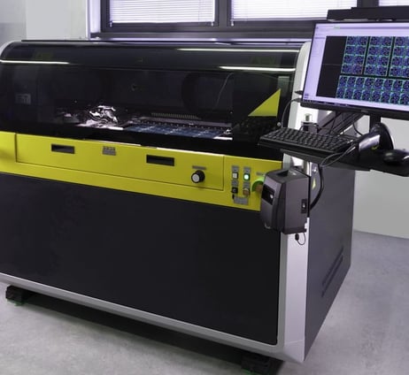

Benefits of Flying Probe Tester
Rest assured the in-circuit testing of a surface mount technology board assembly is fast and efficient with flying probe tester. This tester offers a variety of benefits that conventional test equipment does not. Some of these benefits include fixture-less inspection for quick set up, and proficient testing of misplaced components, faulty components, and poor contacts. Through our unique method of resistance testing, the exclusive solder joint integrity test is able to assess solder joints rapidly, while simultaneously preventing board and component damage through the use of soft-landing feature. Our four terminal measurement function, one that our competitors do not offer, can detect minute differences between inadequate and high-quality soldering. The standard automated optical inspection function is much more reliable than a simple visual check, and will analyze a component’s displacement, presence, and polarity and so on. HIOKI’s flying probe machine test can be executed at a very rapid pace of up to 40 steps per second with a probing pitch of 0.15mm.
Key Features
Ultra-High speed measuring
Measuring rate up to 40 steps per second helps reduce tact times and can actually be used in fully automated production lines averting a bottleneck. This is indeed a unique strength of HIOKI’s flying probe testers.
Fine pitch inspection
Accurately and consistently test down to a lead pitch of 0.2 mm. This allows inspection of fine-pitch components that fixture based testers cannot execute reliably.
Supplementary vision inspection
Supplement overall inspection strategy with our standard vision function allowing for component presence/absence check, as well as polarity and displacement confirmation.
User-friendly interface
A completely revamped Windows based user interface makes use of graphics-rich environment making productivity very intuitive and efficient. Competent and reliable testing achieved regardless of operator.
Wide inspection area
Wide range of board sizes can be inspected from 2″ x 2″ to 20″ x 18″.
Automatic position compensation function
Standard feature working in conjunction with high-precision mechanism that enables probing with extremely high accuracy. Debug process is simple and precise with use of a CCD camera for teaching data coordinates and creating offsets.
A wealth of options
A range of options and accessories available. An optimum system can easily be constructed to cater to customer needs.
Programming methods
CAD conversion software
Manual teaching using CCD camera.
Loading system is standard SPEC
The board loading function is part of the standard package that makes it simple to establish an automatic inspection system. Interface for standard equipment is also provided as standard setup including SMEMA compatibility.
High probing accuracy
Probing accuracy of ±100 µm and movement repeatability accuracy of ±50 µm, ideal for testing fine pitch assemblies for both shorts and open circuits.
Test order optimization
To minimize mechanical travel distance of the probes, the test order sequence is automatically optimized to increase efficiency and ultimately reduce cycle times.
Bad mark detection
The equipped CCD camera can be used for detection of inspection marks used for multiple-sample boards as well as inspection only involving the step of image detection of marks.
Coordinate data teaching
The standard equipped camera can be used for simple and accurate coordinate data input and data revision for debugging.
Flying Probe Tester
Application for EV battery module
flying probe tester delivers high-speed, high-precision, fixture-less testing of battery module with four flying probes. Proprietary flying 4 terminal probes visualize the magnitude of weld defects based on resistance values and enable accurate testing of lithium-ion battery internal resistance.
Flying Probe Tester
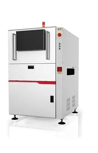

Solder Paste Inspection is the full name of the Automatic optical solder paste detector, is based on the optical principle of SMT solder paste printing quality of the optical detection equipment. During the detection, the PCB information is collected by the optical detection system in the equipment. The acquisition mode is divided into 2D plane mode and 3D stereo simulation mode. The image information is analyzed and calculated by the internal algorithm, and finally the solder paste Quality defects.
Fully automatic non-contact measuring equipment for solder paste presses before the placement machine.
Depending on the plane camera, laser measurement, structured light measurement, programmable stripes and other technical means, the PCB printed solder paste for 2D or 3D measurement (micron precision).
So in the component placement before the solder paste found in the bad phenomenon, which as much as possible to avoid the occurrence of finished PCB failure, is a quality process control meansSolder Paste Inspection is a cutting-edge piece of equipment designed to provide high-precision inspection of solder paste on printed circuit boards (PCBs). This machine is equipped with advanced 3D imaging technology that allows for accurate and reliable inspection of solder paste deposits, ensuring that they meet the required specifications for quality and consistency.
One of the key features of the 3D SPI Machine is its ability to perform inspection on a wide range of PCB sizes and types. This machine can handle PCBs up to 510mm x 460mm in size, making it suitable for use in a variety of manufacturing environments. Additionally, the machine is compatible with both lead-free and leaded solder paste, making it a versatile solution for PCB inspection.
3D Soldering paste Machine is also designed with ease of use in mind. It features a user-friendly interface that allows operators to quickly and easily set up and run inspections. The machine also includes advanced software tools that enable operators to analyze and interpret inspection data, making it easier to identify and address any issues with the solder paste deposits.
Overall, the SPI Machine for Solder Paste Inspection is a powerful and reliable solution for ensuring the quality and consistency of solder paste deposits on PCBs. With its advanced 3D imaging technology, wide range of compatibility, and user-friendly interface, this machine is an essential tool for any manufacturing environment that requires high-precision inspection of solder paste.
Model SSAI-01
Solder paste inspection machine Inspection Module
Camera Specification 5M High-frequency Industrial Camera,High Frame
Pixel 20um,15um(Factory Setting)
FOV 50x40mm 38x30mm (Factory Setting)
LED RGB+TOP
Light Source 0-550 um
Height Inspection Resolution
0.36 um
Height Inspection Accuracy
1um(Based on the actual solder paste/calibration block)
Inspection Item
Volume,Area,Height,X/Y Position,Bridging,Shape,etc
Defective Type
Excessive/Insufficient/Missing paste,Bridge,2D&3D Paste displacement,Shape deformity,Dust,etc
Repeatability(Volume,Area,Height)
<1%@3sigma
GR&R(Gauge Reproducebility and Repeatability)
<10%(@6sigma tolerance-+/-50%)
Inspection Speed
0.35Sec/FOV
Solder paste inspection machine Conveyor&PCB Size
Max PCB Size 510x510 mm
Min PCB Size 50x50 mm
PCB Up-Clearance 30 mm
PCB Bottom-Clearance 30 mm
PCB Thickness 0.5-5 mm
Max PCB Warpage ±3mm
PCB Transfer Height 3 mm
PCB Transfer Height 900+20mm
Max PCB Weight 3KG
Solder paste inspection machine Frame&Others
Base&Frame
Integral steel casting frame,firmly,ensure the high accuracy of inspection
Dimensions and Weight 1080x1360x1600mm(WxDxH) 1200KG/10KG
Power Supply AC 220V 150/60Hz
Power 2.2KW
Communication Interface SMEMA
Air Supply 0.5Mpa
Operating Condition 5-40°C, 15-90%RH
Solder paste inspection machine Options
1.Barcode Reader
Repair Station(PC)
2.3D Calibration Target
5.Infared Muti-touch
3.2D Calibration Glass
6.Offline Editing Software(License Key)
Soldering Paste 3D Inspection machine
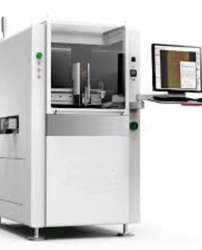

Online high-precision visual dispensing machine, widely used in a variety of high-precision automatic dispensing scenes, combined with high-precision, high speed, high consistency of vision and motion control system, stable and reliable dispensing software, convenient to program the dispensing path, to meet the dispensing needs of different products and different processes.
Materials of phosphor, UV glue, hot melt glue, red glue, silver paste, tin paste, heat conduction, vinyl can be used
-Independently developed vision and motion control systems;
– Support 2D/3D visual positioning and 3D path dispensing;
– Support multi-axis (four-axis, five-axis) linkage;
– Support ontology identification, edge grabbing and other positioning methods to achieve high precision positioning;
– Support platform calibration, multi machine file copy;
– Support weight and density control dispensing process to ensure consistency of glue quantity;
– Support flying dispensing, easy to achieve high speed dispensing;
– Visual dispensing path editing, programming interface friendly;
– Can be equipped with a variety of jet valve, screw valve, needle valve, etc.
– Double rails are supported to improve production efficiency.
Technical Parameters
Model SS-700 SS-800
Electricity demand AC230V 11A 50/60Hz 3KW (No heating rails)
AC230V 11A 50/60Hz 3KW (No heating rails)
Air pressure demand 90psi (6 bar) 90psi (6 bar)
Overall dimensions (W*D*H) 770mm*1200mm*1400mm 880mm*1600mm*1600mm
Weight 650kg 900kg
Axes quantity X、 Y、 Z (U、 R) X、 Y、 Z (U、 R)
Dispensing accuracy Vertical valve (inclined) Vertical valve (inclined)
Positioning accuracy ±30um@3singma(X、Y) ±30um@3singma(X、Y)
Repetition accuracy ±15um@3singma(X、Y) ±10um@3singma(X、Y)
Maximum speed 1000mm/s 1300mm/s
Maximum acceleration 1.0g 1.3g
Drive way Import servo, high precision ball screw Import servo, high precision ball screw
Visual accuracy Subpixel Subpixel
Scouting speed 10ms 10ms
Track load-bearing 3kg 3kg
Track width range 50~475mm 50~595mm
Baseline thickness 0.5–6mm 0.5–6mm
Transportation direction Left–Right (Right–Left) Left–Right (Right–Left)
Protocol SMEMA SMEMA
Single valve (single track / double track) X350*Y470/X350*Y200mm(W*D) X400*Y590/X400*Y320mm(W*D)
Synchronized dual valve (single track / double track) X330*Y400/X330*Y165mm(W*D) X350*Y590/X350*Y320mm(W*D)
Asynchronous double valve (single track / double track) X300*Y430/X300*Y180mm(W*D) X350*Y590/X350*Y320mm(W*D)
Tilt rotary single valve (single track / double track) X250*Y400/X250*Y165mm(W*D) X300*Y540/X300*Y300mm(W*D)
Options Pneumatic injection valve, piezoelectric valve, needle cylinder valve, screw valve, etc
Flying light source module
Track heating module
Laser height measurement module
3D positioning module
Weighing module
Online Glue Dispensing Machine
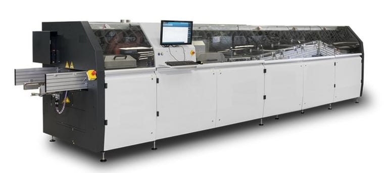

It comes standard equipped with strong conveyor finger, hardly get bent. Good for both bare PCB and also 5kg weight carrier. High-precision, automatic spray fluxing system. The user interface is an Industrial PC and PLC for controlling system, English interface. Can stock numerous groups parameters, provides real-time temperature monitoring. The solder pot can automatically move in & out so if you add another solder pot for lead solder, you can use this machine for both lead free and lead Auto soldering machine is based on customer demand and adopts modular, digital and humanized design. With superiority in function, performance, stability, reliability, security, maintainability, operability and humanization, it not only reduces the operating costs, but also provides qualified products for quality, quantity and production with strong guarantee, it is the peak work in the field of soldering equipment and the best choice and brand product of the customer solders.
High quality heavy double hook titanium finger ,V and L type is optional
MAIN FEATURES
THE FLUX SPRAYING SYSTEM
The Flux Spraying System is perpendicular to the PCB, so it spread more even on PCB and Enhance flux penetrating property to the holes improving the adhesiveness of the solder metal Effectively reduce operating cost.
MODULARIZE SOLDER POT
10mm thickness casting iron solder pot, no easy to deform when heating, perfect contact with heater for more uniform heating, used graphite for insulation for anti-moisture and anti-corrosion The pot is ceramic, coating for a smoother surface, prevent corrosion, longer life time.
CONVEYOR FINGER
Standard equipped with strong conveyor finger, hardly get bent. Good for both bare PCB and also 5kg weight carrier. Specially designed for heavy load carrier.
USER FRIENDLY INTERFACE
Industrial PC and Siemens PLC for controlling system, English interface. Can stock numerous groups parameters. Direct input target temperature into the program Display actual temperature.
1. LCD
• 2. Buffer system
• 3. Flux auto-supply system
• 4. Exhaust fan
• 5. Flux spray system
• 6. Pre-heater
• 7. Solder pot lifting unit
• 8. Dual wave Solder pot
• 9. Cooling system
• 10. Angle adjustment controller
• 11. Finger cleaning system
• 12. Conveyor system
Model NO SSW-350 auto soldering machine SSW-450 auto soldering machine SSW -610 auto soldering machine
Dimension:L×W×H(mm) 4350*1480*1750 4350*1580*1750 4350*1740*1750
Weight 1800kg Approx.2100kg Approx.2600kg
Power Supply 3PH 380V 50HZ 3PH 380V 50HZ 3PH 380V 50HZ
Start up Power 32KW 32KW 45KW
Operation Power Consumption Approx.8KW Approx.8KW Approx.11KW
Control System PC+PLC PC+PLC PC+PLC
Spray Pressure 0.2Mpa~0.4Mpa 0.2Mpa~0.4Mpa 0.2Mpa~0.4Mpa
Exhaust (Top exhaust)+(Side exhaust) (Top exhaust)+(Side exhaust) (Top exhaust)+(Side exhaust)
Exhaust Ducting Diameter(mm) 250 250 250
Exhaust Capacity 30M3/min 30M3/min 30M3/min
Preheating Mode (Convection/IR emitter) (Convection/IR emitter) (Convection/IR emitter)
Preheating Length(mm) 1800 1800 1800
Preheating Temperature (Room temperature)~200 (Room temperature)~200°C (Room temperature)~200C
Warm-up Time(min) Approx.12min(setting:150°C) Approx.12min(setting:150°C) Approx.12min(setting:150°C)
Blower Motor 250W 3PH 220 VAC 250W 3PH 220 VAC 250W 3PH 220 VAC
PCB Width(mm) 50~350 50~450 50~610
Conveyor Direction L-R(Option:R-L) L-R(Option:R-L) L-R(Option:R-L)
Conveyor Speed(mm/min) 500~1800 500~1800 500~1800
Conveyor Height(mm) 750+20 750+20 750+20
Available Component Height(mm) (Top)120(Option:250)(Bottom)15 (Top)120(Option:250)(Bottom)15 (Top)120(Option:250)(Bottom)15
Conveyor Speed Control Mode (Closed loop) (Closed loop) (Closed loop)
Fingers (New Design Double-hook Type)Approx: ①(Spring Pressing
Finger): (2D-40(D-40 Type Finger);(3)(Double-hook Finger); (New Design Double-hook Type)
Option:Fixture claw
Conveyor Angle 4~7° 4~7° 4~7°
Type of solder Pot Motor drive Motor drive Motor drive
Solder Pot Material Casting Iron Casting Iron Casting Iron
Wave Height Adjustment (Inverted)Approx:(Digital Control by PC)
Cooling Method (Air Cooling) Option: (Water cooling)
Heater Power 220V 13.5KW 220V 13.5KW 280V 18KW
Solder Pot Temperature 300℃ 300℃ 300℃
Solder Pot Capacity 480KG 550KG 640KG
Wave Drive Power 180Wx2 3PH 220 VAC 180Wx2 3PH 220 VAC 180Wx2 3PH 220 VAC
Solder Pot Warm-up Time Approx.150min(setting: 250℃) Approx.150min(setting: 250℃) Approx.150min(setting: 250℃)
Finger Cleaning System (Brush) (Brush) (Brush)
Heavy Duty Lead Free Wave Solder Machine
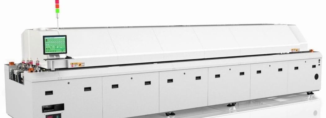

.High Heat Performance : Achieving High Heat Efficiency By Professional Thermal Knowledge And Simulation Of The Matching Between Heat Consumption And Capacity, The Heating Zone Is Shortened And Optimized The Output.
Low Power Consumption : Verified By Theory And Practice, Our Products Are Able To Minimize The Temperature Consumption Between Different Size Of Components In Order To Achieve The Best Heat Evenness.
.Large Size: Can Handle Larger Size PCB Board In The Same Shape And Size Of The Body
Product Features:
Ø Fully Meet All Kinds Of Lead-Free Welding Process Requirements.
Ø Windows Operating System, Global Interface, Easy To Learn Operation; Standard Air Furnace, Hot Air System, Using Hot Air Convection Conduction More Efficient, Faster Heat Compensation.
Ø PLC+PLD Closed Loop Control, Stable And Reliable Performance, High Temperature Control And Curve Repetition Accuracy.
Ø Dual Temperature Sensor, Dual Safety Control Mode, Abnormal Speed Alarm, Drop Board Alarm; Full Modular Design, Faster Maintenance, Reduce Maintenance Time And Cost.
Ø Guide Rail Adopts Special Hardening Treatment, Strong And Durable.
The Regulating Wheel Adopts Single Chain To Adjust The Sequence, Simple And Practical.
Temperature Patrol Instrument Monitors The Temperature Of Each Temperature Zone At Any Time, Ultra-High Temperature Protection, Automatically Cut Off The Heating Power Supply, Nitrogen Quantitative Control In The Whole Process, Each Temperature Zone Independent Closed-Loop Control, Can Make Nitrogen Concentration Range Of 5-200ppm. Double Track Double Speed, Single Cost, Double Capacity, Energy Saving Up To 65%.
In SMT Reflow Systems The Heat Transfer Takes Place By Full Convection. Heated Process Gas (Air, Nitrogen) Is Guided On The Products By Nozzle Plates. The Resulting Temperature Profile Has To Be Conform With Guidelines Of Component And Solder Paste Manufacturer.
The Reflow Soldering Equipment Is Divided Into:
Transmission Part/Heating And Welding Area/Vacuum Unit/Cooling Area And Recovery System
1. Transmission Part
This Structure Runs Through The Whole Equipment And Is Divided Into Three Sections: Heating Area, Vacuum Unit And Stuffy Donkey Section. The Transport Speed Of Each Section Is Adjusted Independently And The Width Is Adjusted As A Whole To Play The Role Of Transporting PCB Board
2. Heating And Welding Area
The Temperature Of Each Temperature Zone Can Be Adjusted Separately To Ensure A Flexible Temperature Curve And Stable Welding Process To Meet The Requirements Of Lead-Free Welding Process. During This Process, The PCB Can Meet The Requirements Of The Customer's Welding Process, Which Is The Same As The Standard Additional Flow Welding Process.
3. Vacuum Unit
At This Time, The Solder Joint Of PCB Board Is In The Molten State. The Vacuum Process Is Started To Make The Vacuum Pressure As Low As 100mbar-10mbar. The Internal Gas Such As Pores And Cavities Can Overflow From The Solder Joint With Dynamic Melting, And The Void Rate Can Be Reduced To Less Than 2%.
4. Cooling Area
PCB Board From The Vacuum Unit Directly Into The Cooling Area, Similar To The Standard Reflow Welding Cooling Function, Meet A Certain Cooling Rate And Reduce The Temperature Of The Plate, Into The Next Process, At This Time The Welding Process Is Completed.
5. Resin Recovery System
With The Same Function As Standard Reflow Soldering, The Resin Is Recycled Into The Specific Structure Through Cooling, Regular Maintenance, Reducing Equipment Maintenance And Environmental Pollution
Heating System of hot air reflow oven
Heating Zone Structure 12 heating zones, 24 heating modules
Heating length 4440mm
Cooling type Dual cooling, enforcing cooling
Outlet diameter 2-145, Exhaust demand 20-25m3/min*2
Conveyor system of hot air reflow oven
Component width min50mm-max400mm
Conveyor direction Left-right/ right to left
Conveyor height 900±20mm
Fixed rail side Front rail fixed( Optional end rail fixed)
Conveyor type Chain + Network with synchronous transmission
Component Height Clearance above 30mm, clearance below 20mm
Conveyor speed 350mm-1500mm/min
Control system of hot air reflow oven
Power source AC3 5W 380V 50/60Hz
Total power 89KW
Start up Power 40KW
Operation power 11.5KW
Temp. control range Room temperature to 320℃
Control type PC+PLC control system
Guide line width Mode Electric+Manual
Temp. control accuracy ±1℃
PCB temp. distribution deviation ±1℃
Data storage Process Data and status storage
Power-off protection Equip with UPS
Operation interface Windows English
General configuration of hot air reflow oven
Dimension(L*W*H) 6490*1372*1450
Weight 2800-3000kg
Machine color Bright wrinkled white
